Tuesday, May 23, 2017

Day Twenty - Impedance 5/16/17

Hello guys, today we talked about impedance, which is the resistance in AC circuit.
The one special thing about impedance is the ability of making a phase shift.
For resistor, there will be no phase shift, but for capacitor and inductor, there will be phase shift due to its imaginary part impedance.


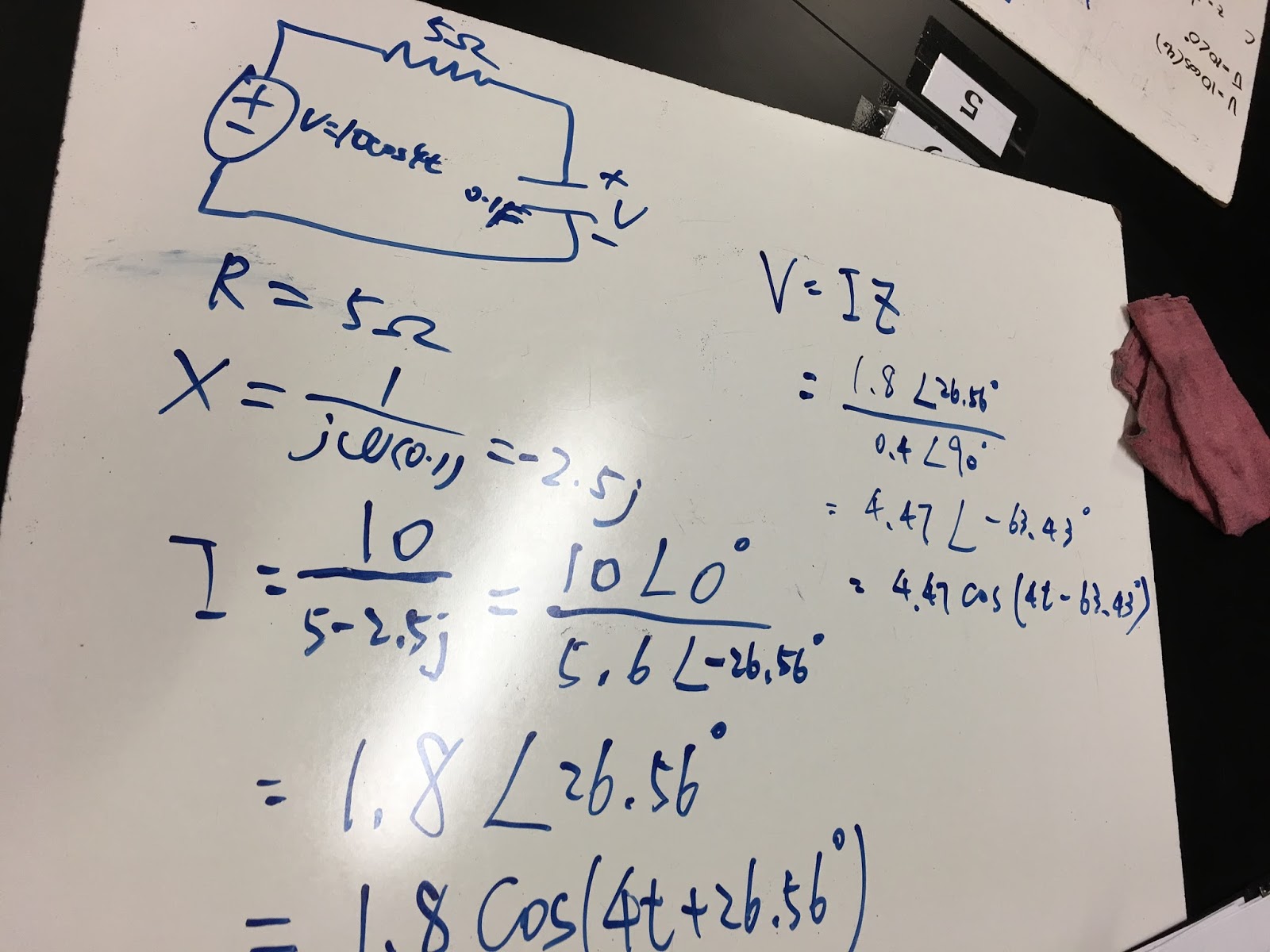
Here is an example of how we calculate the impedance of the capacitor and the alternating current going through it.

Pre-Lab:
For the circuit in the pre-lab for 5k Hz waveform, the calculated voltage and current for 47ohms plus 100ohms resistors is listed in one. The calculated voltage and current for 47ohms resistor and 0.001H inductor is listed in two. The calculated voltage and current for 47ohms resistor and 0.1microFarat capacitor is listed in three.

Lab:
For 5k Hz:
Our measured current is 13.27mA for 100ohms resistor and measure voltage is 1.367V.
There is no phase shift.

Our measured current is 34mA for the inductor and voltage is 1.06V.
There is a phase shift of 32.5 degree.

Our measured current is 6.2mA for the capacitor and voltage is 2.05V.
There is a phase shift of 82.8 degree.

Comparing the current and voltage:
Summary:
From our lab, we can conclude that there are phase shifts in circuits consisting of capacitor and inductor. Using the phasor analysis, we can precisely calculate the max current and max voltage in the given circuit element. It is important to note that the phase shift is also calculated, and it can be represented as the phase between voltage and current.

Sunday, May 14, 2017

Day Nineteen - Phasors: Passive RL Circuit Response 5/11/17

Hello guys, today we talked about Phasor. wow.
Phasor is usually used in AC analysis.
Phasor is usually represented by complex number (rectangular), polar form R(angle), and exponential form.

In our calculation, the phasors are always calculated through the rectangular and polar form.

Note that, when we are adding the phasors together, phasor with different frequency(or omega) can not add up together.

This cheatsheet is very important.

Lab:

Pre-Lab
The cutoff frequency for 1mH and 470Ohm resistor is 47000/2Pi = 7480Hz
The frequency with one tenth of cutoff frequency is 748Hz
The frequency with ten times of cutoff frequency is 74800Hz

With ten times the cutoff frequency, the phase difference is (3.102)/(13.5)*360 = -82.72degree,
and the gain is 2.155(mA)/223.2(mV) = 0.009655
With the cutoff frequency, the phase difference is (16.87)/(135)*360 = -44.9degree,
and the gain is 13.28/668.3 = 0.01987
With one tenth of cutoff frequency, the phase difference is (0.03)/1.45 = -7.448degree,
and the gain is 0.001675/1.013 = 0.0016535

Comparing our calculated values with measured values:
From the data, I can conclude that we successfully finished the lab, especially on the phase difference, we have an excellent data. However, things can improve, especially on the small angle. For the small angle, a more precise data can be achieved for analysis for less error.

Summary:
Today, we talked about phasor for AC circuit analysis, and we finished the lab which describe the nature of phasor. The phase difference occurs depend on the element in the circuit. and with different frequency, we may have different phase difference and gain.

Day Eighteen - RLC Circuit Response 5/9/2017

Hey guys, today we talked about Schmitt Trigger, which can be used to filter out the noisy input signals by simply giving two threshold voltage.
Here is the schematic of the simple Schmitt Trigger circuit:
In practice, the real Schmitt Trigger will look like this:

Then, we had a review on the RLC circuit. And a practice problem is shown below.
 
Lab
PreLab  

Using this differential equation, we can find the damping ration and natural frequency of this circuit.

 Our calculated damping ratio is 1563.8 and natural frequency is 10105.8Hz

This is how we implement the circuit.

Our estimated damping ratio from the graph is 0.25, rise time is 2.15*10^-4, DC gain is 8.

Summary:
Today's lab gives us an idea that not all RLC circuit will be put in series or parallel; therefore, we have to derive differential equation from the circuit instead. By using the differential equation, we will still be able to calculate the damping ratio, frequency, etc.

Day sixteen - Exam Day, Day seventeen - Series RLC Circuit Step Response 5/2/2017

Hey guys, today we talked about the second order differential equation, which is RLC circuit. From the name of the circuit, we can know that this circuit consists of three elements, resistor, inductor, and capacitor.

In order for step response to occur, we first assume that certain voltage source is applied to the circuit before.

For RLC circuit, there are some values we have to find first.
They are the very important values we have to find in order to solve the problem.
It is important to remember that the v and i are correspond to the capacitor voltage and inductor current.
In addition, there are two convenient ways to find the v(0) and i(0), which are using the facts that the voltage across the capacitor can not rapidly change and the current across the inductor can not rapidly change.

Lab

Pre-Lab
This is the differential equation, damping ratio, natural frequency, and damped natural frequency of the circuit in the lab.
Lab Result
This graph is showing we have successfully implement this lab. We can see the transient and steady state parts of the Vout.
Our estimated rise time of the circuit is 1.241ms. Note that the rise time of the circuit is the time between the point where the Vout increases rapidly to the point where Vout meet the first steady state voltage.
Our estimated overshoot time of the circuit is 3.5ms, and our estimated oscillation frequency is 42.58 microsecond (23485Hz) .
Here is the way we find the rise time and overshoot.
At the beginning (in transient), the DC gain is 2.383.

Summary:
From today's lab, we have experienced the step response of the RLC series circuit, in our special case, the Vout is a under-damped response. One point to note is that even the Vin is still connected to the circuit while connecting data from Vout, the transient and steady state response can still be attained. Look at the Vout graph we have, the overshoot of Vout is larger than our input voltage, which means that we can use the step response to create a sudden, huge amount of voltage output, such as car ignition system. Very important point is to note that the sudden changing voltage is caused by the sudden application of a dc source. The solution of the equation must have both transient and steady-state response.