
Using mesh analysis with KVL to solve the circuit.
After that, we have our first experiment using mesh analysis.

From our calculation, we expected V1 to be 5volt and I1 to be -0.3224*10^-3.
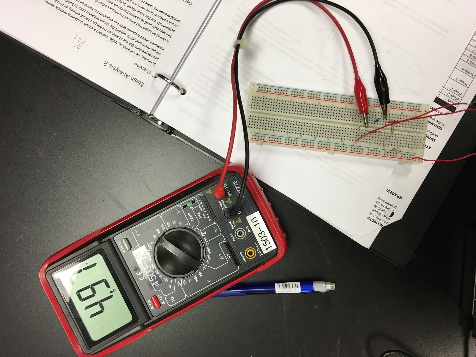

Percent error is very low for this experiment (-0.6% and 0.7%).
After that, we had our design problem of the transistor.
Since the larger the transistor, the more heat it can take but also the more expensive the transistor, we have to calculate the power output of the transistor before using it because like I said, if the power is larger than the maximum amount the transistor can take, the transistor might blow up.

After this calculation, we had our second lab, time varying signals, which purpose is to show the oscillation of the voltage.


Sinusoidal wave

Square wave

Triangular Wave.
We can see the different shape of the wave. The square wave has the fastest rate of change.
Summary: Today, we talked about mesh analysis and how to implement it into the real circuit.
We also learned about transistor and how to design the circuit if we want to put a transistor into the circuit. The bigger the transistor, the more power input it can handle, however, it will be more expensive at the same time, so designing a circuit with appropriate size of transistor is important.
After, we also learned the different shape of the voltage graph. It depends on the pulse of the time varying machine.
No comments:
Post a Comment